In my role as the Technical Director for the production of The Wild Party by Andrew Lippa, I undertook the challenge of designing and executing a custom automated stage elevator. This elevator was a critical element for allowing for seamless actor transitions to and from the stage. It also represents the most extensive and detailed automation system I had ever designed, requiring a substantial effort to research and safely execute the project. The elevator was designed as a wire rope-driven system, with a double-purchase counterweight and was powered by the Creative Connors Spotline lifting winch. Its design included a 4' x 6' platform with a transparent acrylic floor, enabling the projection of light upward through the platform via two moving lights underneath. If you're interested in learning more about the production in which this elevator played a pivotal role, please click on the following button:

Fabrication began with the lift bed itself. It was constructed from 1" 16ga box tube with 1.5" x .25" L-angle to terminate the lifting lines, and 3" SCH 40 pipe to redirect the cables to the termination points. Because we had limited arbor space and hoist capacity, this design was supposed to be strong and light to allow for the most amount of acting weight as possible. This frame was welded out of square by 3/4" of an inch and needed extra attention during installation which which we accommodated through custom milled UHMW guide blocks on the columns.

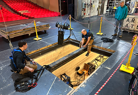
As we began our load in process, we had to remove two 4'x8' platforms from the stage deck as well as the I-Beam running across the gap to allow for the proper placement of the lift bed. We rigged a 1/4 ton chain hoist to easily lift and remove the beam and we sat a custom plug in its place to frame out the lift. We began with the trap so we could proceed loading in the elevator below and so the set above would not trap us in later on.

A major problem we ran into with this build was the lack of accounting for friction in the system and the amount of weight we would need. Because of the 2 : 1 counter weight and 500lb lifting capacity of the winch, the friction that we did not account for added almost 50% more weight into the system because of the 5% friction factor from the ball bearing sheaves. I tried to make the arbor as compact as possible to allow for the most travel but it ended up being too tall for the allotted space. Because of its size, travel was limited and the lifting bed fell short about 8" to the deck height. We accommodated this with an extra step on the lift, but should have created a shallower and wider arbor to hold more weight.

This was the clew I designed in the system. The two cables coming from the bottom left were the line that connected to the arbor. I decided to use two lines to create redundancy in the system. The four lines leaving the clew on the top right lead to the elevator bed and are the four lifting lines of the system. This was designed with the through bolts so the weight of the system was relying on engineered bolts instead of welded connections. Lastly, these UHWM blocks were custom milled to fit this frame and allow for smooth movement. If you note the two crimps on each cable termination, we used an electric swager on the 1/4" cable which calls for two crimps only.

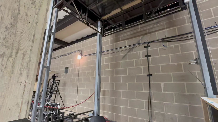
A design challenge I faced was how to secure the counter weight arbor to the I-Beam above. I knew that the beam was rated for 14,000lbs (far above our needs), so the difficulty was the attachment method. I ended up using 1/4" flat stock to create a pinch plate with 2" x 1/8" thick box tube running perpendicular to the beam. From there, it was easy to bolt and attach the rest of the hardware to the pinch plate. This method proved helpful because we were able to loosely set the components on the beam and slide it into position before securing in place.

This image details the close proximity of cables, sheaves, and hardware to each other as the cables are routed to their respective sheaves. This area was difficult to design because of the incoming cables from the arbor to the elevator bed and the amount of space I had to work with. In this image, eight cables are being routed to the elevator, four to lift, and four to lower. All of the plates you see which make up the pulley's, we already had in stock as a student previously water jet all of the components in a previous year. Over 45 sheaves were used to create this system.

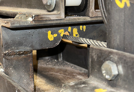
This closeup shows the "down" line from the arbor running to the hoist. This is also a perfect time to showcase my welds! Either my model was off, or I messed up during fabrication but this wire ran directly through the steel of the frame. To avoid the rubbing, fraying, and potential damaging of the wire rope, we used a pneumatic die grinder to free the cable from rubbing and create a channel through the steel.

To secure the pulley and routing frames to the floor, we used 3/8" concrete wedge anchors. If you look closely at the bottom rail of the frame, there are two additional holes drilled through the angle iron. This was to provide additional connection points incase an anchor broke off in the ground and we needed other means of bolting. This proved helpful as two of our anchors broke off during installation. In the future, I would consider bracing the frame the I-Beam above to create redundancy and prevent total reliance on the anchors.. This photo also showcases the fleet angles and positioning of the sheaves.


